The Racks view gives you an overview of your racks – which room they reside in and the number of devices they contain. This interface is also the homepage of dRACKula.
1. Add, Edit & Remove a Rack
Before you are able to create a rack, make sure you have properly configured at least one building. (See Configuration.1)
a. Add a new Rack – Click on the Add a Rack button at the top of this tab to open the new Rack form. Rack names must be unique.
b. Edit an existing Rack – Click on the icon to the right of the rack name to open the edit form.
c. Remove a Rack – Click on the icon to the right of the rack name to remove the rack. (NOTE: All devices located in the rack will be “unracked”.)
2. Rack Physical View
The physical rack view (screenshot below) shows the contents of a rack. You can get here through the Racks interface by clicking on the various rack names. Alternatively, you can get here anytime by selecting a rack from the dropdown menu on the toolbar (See Interface Basics.1).
Initial entry into this view will show the graphical representation of your rack (as seen above) with the front of your rack (A) on the left and the back of the same rack (B) on the right. PDU’s configured to this rack will be shown in the middle (C). To configure PDU’s, see the Managing PDUs section of this User Guide. There is also an icon button to the right of each slot (D). If a slot is empty, you will see the Add () icon. Otherwise you’ll see the Options () dropdown icon. Clicking this button will provide a set of actions you can take to alter the device in the slot.
Alternatively, you can rack/move a device using the Device Tree (as shown below).
The Device Tree (A) contains devices across all datacenters, as well as all unracked devices. To rack/move a device, simply drag the icon associated with the device from the tree into the slot desired. As soon as you initiate the draggable element, you’ll notice the element will turn into the hardware faceplate and the available slots on the rack will change color. Consequently, you’ll notice the slot will turn green once you hover the device over it (B). Once the slot is green, it is safe to drop the device. Note: If you are moving PDUs located in a separate rack, all devices plugged into the PDU will be unplugged.
If you are working with live racks, you will only be able to add devices already configured in the Device interface (See Managing Devices).
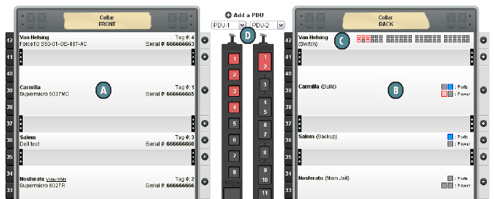
Using the view option section of the toolbar, you can switch from a graphical to a detailed representation of the rack (as seen above). This view displays the specifications of each device as you described them. The identifier is the device name, which is shown on both front and back views. Specifically on the front (A), you’ll see the Manufacturer, Model, Asset Tag # and Serial #. On the back (B), you’ll see the role of the device, ports, power and individual monitoring tools specific to the device. If the device is indicated as a Switch (C), you’ll see the port layout of the particular switch. The PDUs (D) will show the plug layout. The middle of the PDU will show Load specifications (Max Load and Current Load) measured in amps and volt-amps. Red plugs indicate that the outlet is used and hovering over will show which device is plugged into it.
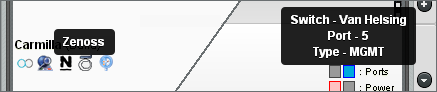
Furthermore, hovering over each icon on the page will show you specific details for that element (as shown above). For example, hovering over a monitoring icon will show you which monitoring tool the icon represents. Hovering over ports or power boxes will specifically show where the cable is plugged into. You will also notice some different colored boxes in the Ports and Power section in this part of the interface –
- Ports
- – Indicates a management port.
- – Indicates all other network ports.
- Power
- – Indicates a plugged power supply.
- – Indicates the potential for a dual power supply.
3. Rack Prototypes
Prototyping a rack allows you to design racks without being constricted to available devices. Using this option is extremely useful when planning rack layouts as it provides the ability to design port and plug layout as well as giving you an estimated power consumption based on the model of the device. To create a prototype rack, simply add a rack as you regularly would and check the Is Prototype checkbox in the add form. Additional features in the prototype interface includes Rack Diff, which compares a prototype to a live rack and displays a changelog based on the differences, and Promote to Live, which allows you to promote a prototype rack to live by swapping in available devices. We will cover these features in this section.
a. Interface Basics
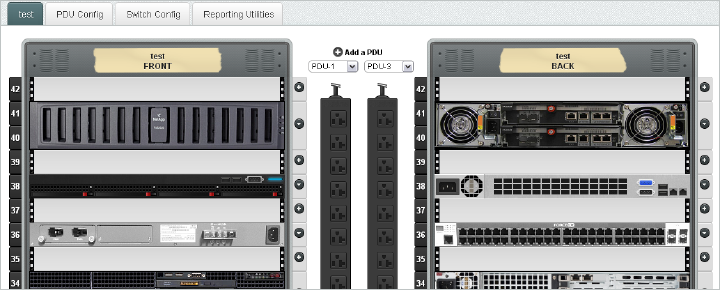
The prototype interface (as shown above) is very similar to the live interface – with two major differences. Since prototypes have the ability to add devices that are not configured through the Devices tab, all prototype racks handle their data through their own interface. You will find that the tab layout (A) is much similar to certain toolbar tabs.
b. Rack Diff
Located in the Reports tab, the Rack Diff feature compares a prototyped rack to a live rack and produces a changelog based on the differences. This proves extremely useful when you have passed the planning stage of a rack upgrade and are ready to make physical changes – the changelog will help to show you exactly what you need to do once you are in front of the rack.
To produce a changelog, simply click the Rack Diff button at the top of this tab, select the live rack you wish to compare it to and click Compare.
4. Cloning a Rack
Cloning racks allow you to plan changes to an existing live rack. This proves useful when you are antisipating major swapouts and need to formalize a layout before making changes. To clone a rack, click the Clone () icon located on the right of the rack name in the Racks tab, provide a name, and the cloned rack will be created under the Prototypes section.